Most consumer devices have some way of debugging for the ease of development of the board (JTAG). Most routers, and other network devices have a serial console connection as well.
I’m pretty sure this Belkin device also has one, in this blog post I will show you how I locate serial console ports on consumer devices. A basic serial console connection consist of the following pins:
– RX pin, the receiving pin as seen by the device (in this case the data the Belkin receives from the PC)
– TX pin, the transmitting pin as seen by the device (in this case the data send from the Belkin to the PC)
– GND pin, the ground connection between the device and the PC.
– 3.3V/5V pin, a constant power supply.. in most cases this is not needed. But you could use it to power a MAX232 chip.
The first step is to visually look at the board, most serial connection headers are 4-6 pins. Do you remember the 6 pin header I described in the previous blog post?
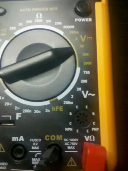
So, this is going to be our target. The second step in the process is to find the ground (GND) connection of the serial port header. To do this I prefer to use a multimeter (with continuity tester functionality), the continuity test function looks like this:
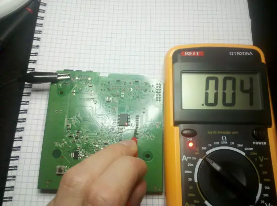
The test will beep and/or visually indicate whether two electrical connections are connected to one another. Knowing that the continuity tester function can do this, it’s rather easy to find the ground connection. You need a reference pin for the ground connection (I used the dc-jack ground connection) and then test each pins of the header on at the time.
Aha! Pin 6 is the ground connection.
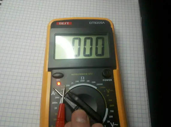
Now that we found the ground connection we can proceed to the next step, which is finding the VCC (+) connection. Usually this is 3.3v or 5v. For this step we use the multimeter once again, but now on the dc-voltage setting. Something in the range of 5-20v should be good:

Multimeter for dc voltage measurement
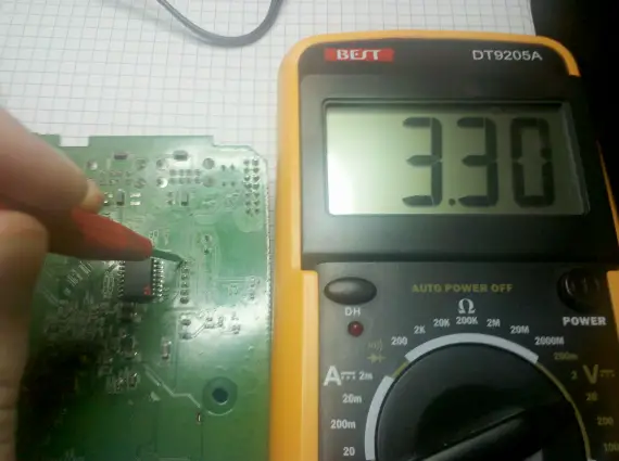
Leave the ground clip connected to the same reference point as we used in the previous step. Now touch each of the pins on the header to check for a voltage, looks like I found something:

Found the 3.3v (+) connection!
So pin 1 is the 3.3v connection. This post will continue later on for the sake of readability. In that future post we will figure out the TX (Transmit) and RX (Receive) pins.
One thought on “Finding a serial console on the Belkin Home Base”
Comments are closed.
Recent Posts
The time is finally come! Samsung have released their Galaxy Watch 4 series of watches. It features Google Wear OS 3. and it comes in two models, being the standard model and the watch 4 classic. In...
Microsoft 365 Defender cross check with on-premises Active Directory
Recently I was reviewing the new Microsoft 365 Defender portal and I noticed that a few endpoints were missing from the device inventory. This got me thinking that it would be great if I could...


Nice post!
Looking forward to the next part!