Today I received a package from Seeedstudio, containing some components and yes, also a bus pirate. The Bus Pirate is an open source hacker multi-tool that talks to electronic stuff. Some information about it’s features can be found here: http://dangerousprototypes.com/docs/Features_overview
To test the functionality of the bus pirate, I used a BMP085 pressure sensor chip. This chip allows you to measure barometric pressure, as well as temperature. This chip uses the I2C protocol, a protocol that “talks” between chips (for example, a microcontroller and a sensor).
I2C can be analyzed with the bus pirate. Enough introduction, let’s start by practice.
This is how I connected the bus pirate to the BMP085:
| Bus Pirate | BMP085(pin) |
| MOSI/SDA | SDA (7) |
| CLOCK/SCL | SCL (6) |
| +3.3volts, Vpullup | VDDA, VDDD (3,4) |
| GND | GND (1) |
The pullup connection is required because the I2C protocol uses pull-ups. You can read more about pull-up resistors on Wikipedia.
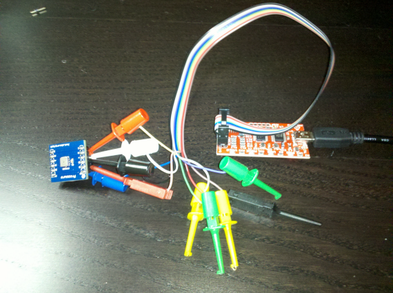
This is a picture of my setup (I used a BMP085 breakout board):
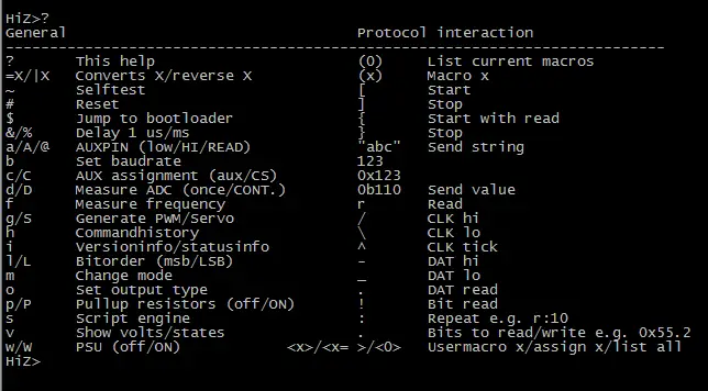
After I got the hardware setup, I was ready to connect the bus pirate to my PC. This was quite easy, by installing some USB to serial device drivers. You then connect up to the virtual serial port just created. You should see this:
(I used the ? command to display some command information)
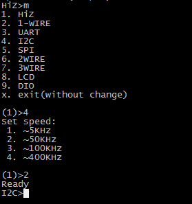
As we are going to analyze an I2C device, you need to change the hardware type to I2C, this is done using the “m” command:
In the I2C context, we need to enable the pull-up resistors.. as well as the power supply:
The (1) macro command allows you to search for I2C devices on the bus:
Aha, two “devices” are found.. a read and write address for our BMP085! I double checked this information (read and write addresses) with the information found in the datasheet:
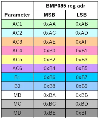
We are now ready to write/read data to the I2C bus. The BMP085 has 11 registers with calibration data, those are listed in the datasheet:
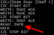
Let’s try to read register 0xac, one of the calibration registers:
The command sequence is as follows:
[ – indicates a start bit
0xee – is the write address of our device
0xac – is the register we want to read
[ – indicates a new start bit, to start a new command
0xef – is the read address of our device
r – command to read one byte
] – indicates a stop bit
0xFB is the value of register 0xAC.
This concludes my first blog post about the bus pirate, I hope this helps other people out there to get started reading I2C devices. I want to create a python script to read out some truly useful information from the sensor later on.
3 thoughts on “Bus pirate: “talking” to chips (BMP085 used as sample)”
Comments are closed.
Recent Posts
The time is finally come! Samsung have released their Galaxy Watch 4 series of watches. It features Google Wear OS 3. and it comes in two models, being the standard model and the watch 4 classic. In...
Microsoft 365 Defender cross check with on-premises Active Directory
Recently I was reviewing the new Microsoft 365 Defender portal and I noticed that a few endpoints were missing from the device inventory. This got me thinking that it would be great if I could...



Very informative, thanks!